Arduino I2C Tutorial Communication Between Two Arduino Boards


About Arduino I2c
Hardware Design. Built-in Libraries. Contributions. Home Learn Inter-Integrated Circuit I2C Protocol Arduino I2C Pins. Below is a table that lists the different board form factors and what pins are for I2C. Form factor SDA SCL SDA1 SCL1 SDA2 SCL2 UNO SDAA4 SCLA5 Nano A4 A5 MKR D11 D12
In this tutorial, we'll discuss Arduino I2C Communication from the very basic concepts all the way to implementing Arduino I2C-based serial communication. We'll create a couple of Arduino I2C projects in this tutorial, the first of which will be Arduino with I2C LCD 162 interfacing. It acts as if it's a hardware I2C that's
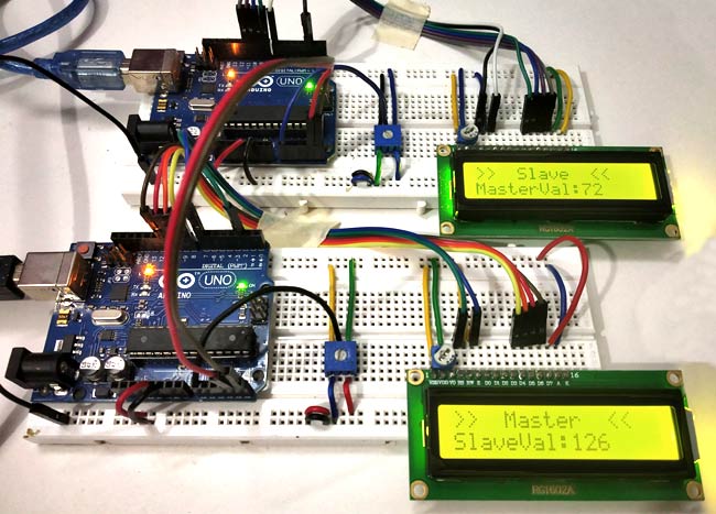
This project will read the position of a potentiometer connected to a master Arduino, send the information over I2C, and change the blink rate of the LED on the slave Arduino. Arduino I2C Pins. The Arduino has dedicated pins for I2C, which have built-in pull-up resistors as required by the I2C protocol. For Arduino Uno boards, these are pins A4
Essentially I have couple Arduinos communicating via I2C, thats working fine. One Arduino is a master and requests data from all the slaves around 20 times a second. One of the Slave arduinos has 2 interrupts attached to it INT0 and INT1, INT0 is reading a pulse signal up to 13 Khz, INT1 is also reading a pulse up to 200 Hz 0.2KHz along with
With Arduino can create large number of projects as you have seen if you read Hwlibre, programming the microcontroller in a simple way.But between the analog and digital connections of this board hardware libre, there are some that are still somewhat unknown to many beginners, such as the true potential of the PWM connections, the SPI, the RX and TX pins of the serial port, or the I2C bus itself.
Arduino and I2C Hi there, Welcome to our Instructables page. Here we will talk about I2C communication between two Arduinos. After we have connected the hardware properly now it is time to start the programing. For enabling the I2C communication we will need WIRE LIBRARAY, which should come with Arduino programing tool by default.
The I2C bus in Arduino. Arduino has I2C support by hardware physically linked to certain pins. It is also possible to use any other group of pins as an I2C bus through software, but in that case, the speed will be much lower. The pins to which it is associated vary from model to model. The following table shows the arrangement in some of the
I2C LCD Display Pinout. The I2C LCD display has four pins, simplifying connections and reducing wiring complexity GND Ground pin should be connected to the ground of Arduino or external power source.. VCC It should be connected to the 5V output of the Arduino or a 5V external power supply.. SDA Serial Data This is an I2C data pin. SCL Serial Clock This is an I2C clock pin.
Here, we are going to use the Wire library to start up the I2C communication between our Arduino Micro and the MCP4728 DAC. In our void setup section, we are going to initialize the communication line between the Arduino and the peripheral device by using Wire.begin, which begins the transmission of data between the Arduino and the MCP4728.
We demonstrated the inner workings of I2C along with its protocol. We also listed down its applications, advantages, and disadvantages. Lastly, we made sample codes demonstrating the functions of I2C on an Arduino, relating them to the actual I2C protocol. Learning the basics of I2C will be very useful for your projects requiring I2C interfaces.