Arduino And MAX7219 LED Dot Matrix Display Interfacing Tutorial


About Arduino Screen
Find deals and compare prices on arduino matrix led at Amazon.com. Browse amp discover thousands of brands. Read customer reviews amp find best sellers
The Arduino UNO R4 WiFi comes with a built in 12x8 LED Matrix, that is available to be programmed to display graphics, animations, act as an interface, or even play games on.. Goals. The matrix and its API are developed to be programmed in a few different ways, each suited for different applications. This guide will walk you through the basic concepts for programming the LED matrix, and get
Arduino LED Matrix Code - Scrolling Text. When you want to print a long message that is too long to fit on a LED matrix display, you can use the scroll text effect technique. The below Arduino code shows how to scroll a message on the LED matrix display.
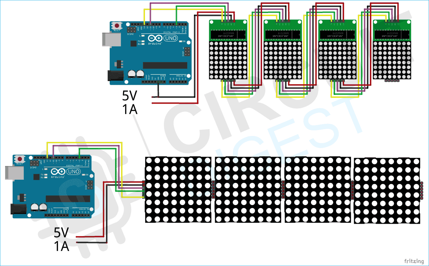
Connecting an LED matrix to the Arduino is a lot simpler with a breakout board that has the MAX7219 already connected to the display. These are the parts you will need Arduino Uno Jumper wires 88 LED matrix breakout board Follow this wiring diagram to connect a breakout board display to the Arduino
Sending Bytes to an 8x8 LED Matrix. 298 respects. lights. art. Components and supplies. 1. USB Cable - Standard A-B for ARDUINO. 2. Breadboard generic 1. Arduino UNO. 16. Jumper wires generic 1. 8x8 LED Matrix. Apps and platforms. 1. Arduino IDE. Project description. Code. If the pins are set to input 68 the display will be very
The MAX7219 chip is a popular solution for using dot matrix displays with Arduino. It can control LEDs through serial data commands and allows chaining multiple displays to create a large screen. Dot Matrix Display. Typically consists of an 88 matrix with 64 LEDs. Has a 16-pin connection, where 8 pins control the rows and 8 control the columns.
Arduino LED Matrix Display Recently I saw video of Great Scott, where he made 10x10 LED matrix using ws2812b RGB LED diodes. Serial folder, and open Arduino code. Change the number of LEDs and pin in the code. Upload the code and close the Arduino IDE. Open LED Matrix Control software. Chose COM port and go to the draw mode in the upper
LED Dot matrix driven by MAX7219 works perfect with Arduino. Code samples. Samples below implement this animation These samples use a LedControl library for the MAX7221 and MAX7219 Led display drivers to switch LEDs ONOFF. Matrix as a 64-bit long integer. State of the 8x8 matrix can be presented as an unsigned long integer uint64_t.
The 16 pins of the matrix are hooked up to 16 pins of the Arduino board. Four of the analog pins are used as digital inputs 16 through 19. The order of the pins is assigned in two arrays in the code. Two potentiometers, connected to analog pins 0 and 1, control the movement of a lit LED in the matrix.
Its a tutorial about a dot matrix module. 88 LED Matrix Tutorial Project Code and Schematic. 10 respects. diy. dotmatrix. arduino. Components and supplies. 1. LED Dot Matrix Display, Red. 1. Arduino Nano R3. Apps and platforms. 1. Arduino IDE. Project description.
Building an LED matrix display with Arduino is an exciting project that blends creativity with technical skills. Whether you're a beginner or an experienced maker, this project offers endless opportunities to innovate and learn. The beauty of an LED matrix lies in its versatility. From simple patterns to complex animations, the only limit is