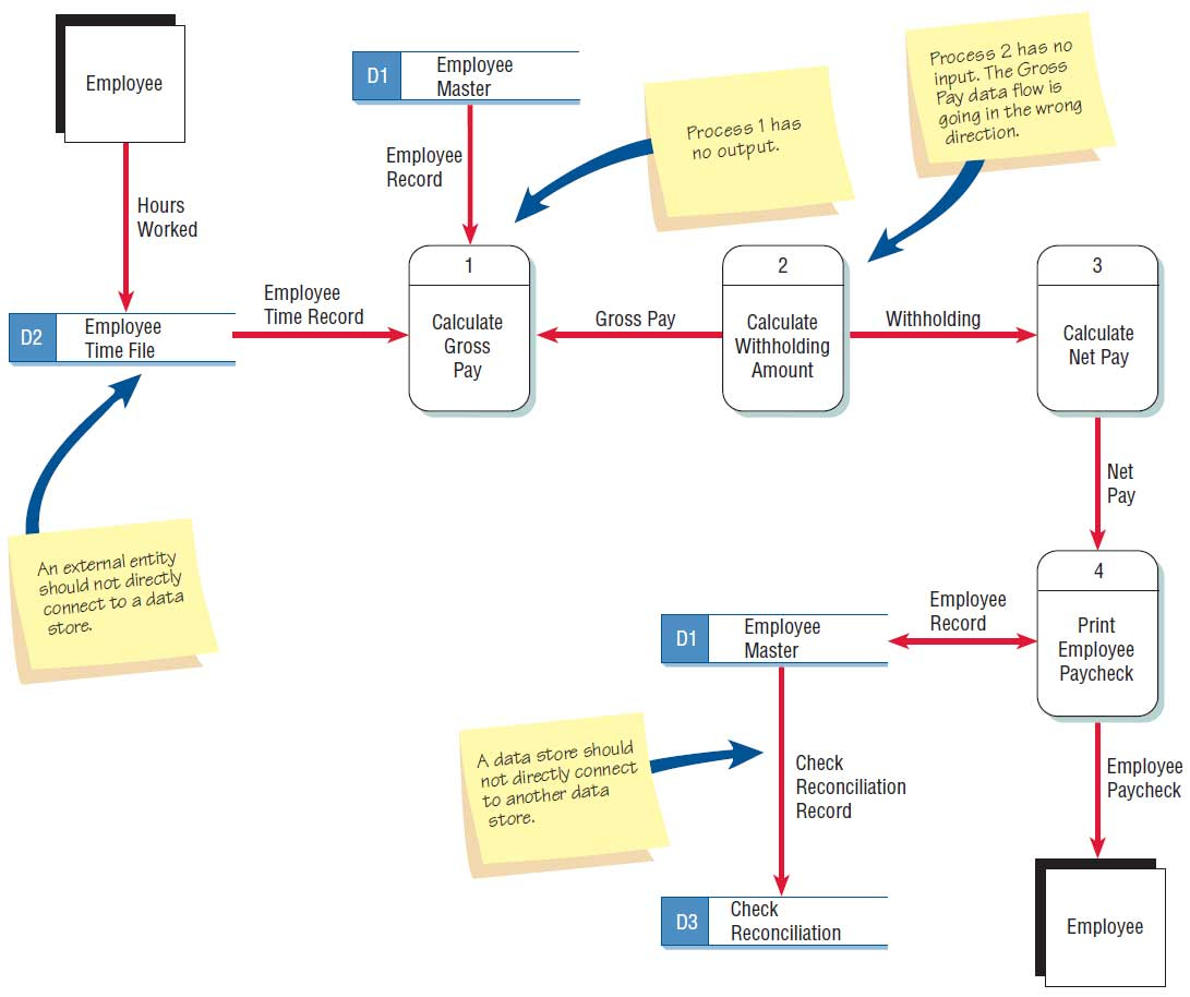
Entity Flow Diagram ERModelExample.Com
About Entity Data
Data Flow Diagram is a visual representation of the flow of data within the system. It help to understand the flow of data throughout the system, from input to output, and how it gets transformed along the way. Like in a Banking software system, it is used to describe how data is moved from one entity to another. Logical Data Flow Diagram
In the New Diagram window, select Data Flow Diagram and click Next. Enter Context as diagram name and click OK to confirm. We'll now draw the first process. From the Diagram Toolbar, drag Process onto the diagram. Name the new process System. Next, let's create an external entity. Place your mouse pointer over System.
A data flow diagram shows the way information flows through a process or system. Whether you are improving an existing process or implementing a new one, a data flow diagram DFD will make the task easier. Nearly every process or system begins with input from an external entity and ends with the output of data to another entity or database
What is an Data Flow Diagram DFD? Learn about data flow diagram symbols and DFD levels and types. Read the data flow diagram tutorial. See DFD examples. Label the arrows with the name of the data that moves through it. External Entity Notations. External entities are objects outside the system, with which the system communicates.
Data flow diagrams DFDs, on the other hand, are generally used to show how data moves through a system, emphasizing data flow and processes rather than detailed software behavior. These symbols make it easier for your team to read and understand your diagrams. External entity. External entities are actors, sources, sinks, or terminators
Data flow diagrams are important because they make it easier to understand the flow of information through complex systems or processes. By visualizing the components of an entire system, DFDs can help users An external entity could be a person, organization or system. For example, a customer could be an external entity in a DFD that
Context Data Flow Diagram Level 0 This high-level overview uses a single process to represent the entire system's functions. An example for a Clothes Ordering System is illustrated below Steps for Creating Context DFD Define the process. Create a list of external entities. List data flows. Draw the diagram. Level 1 Data Flow Diagram
Otherwise, it means you're allowing an external entity access to your data files and stores. 7. The labels of processes can be verb phrases. Data stores are displayed by nouns. Context data flow diagram definition and example with explanation. When it comes to simple data flow diagram examples, context one has the top place.
Data flow diagram DFD is a graphical representation method used to depict the flow, storage, processing of data in a system and the interaction between external entities. This article will systematically explain the components, types, application scenarios, drawing tutorials, etc. of data flow diagrams, and share multiple examples, hoping to help you understand data flow diagrams.
External Entities - An external entity can be a person, organization, or system that is external to the system. From entities, the information flows into the system also known as a source or the entities receive data from the system also known as a sink. Level - 1 Data Flow Diagrams - Level - 1 DFD decomposes each parent process


