Arduino Joystick Breadboard With LCD Output 5 Steps With Pictures


About Lcd Connection
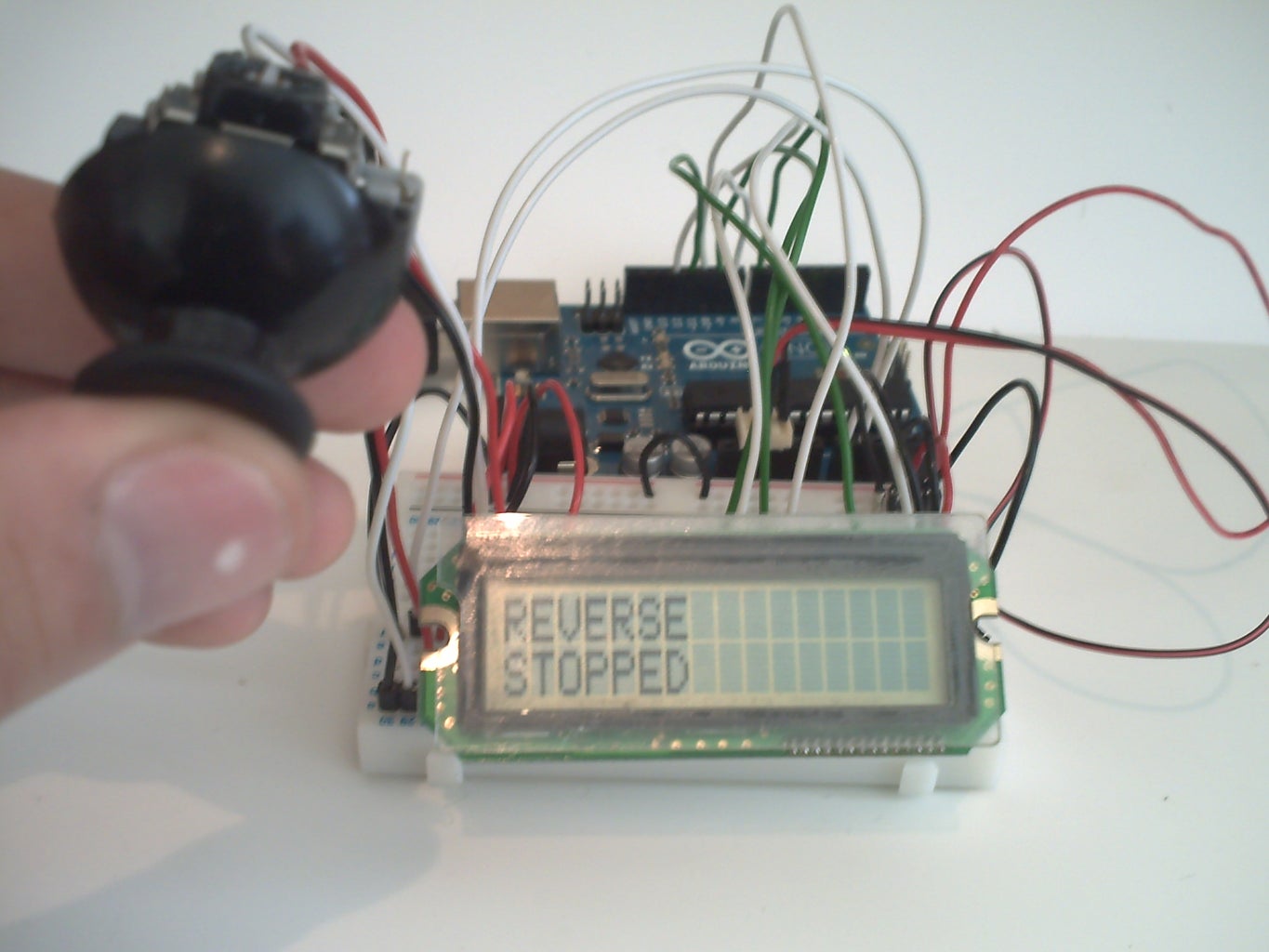
Before wiring the LCD screen to your Arduino board we suggest to solder a pin header strip to the 14 or 16 pin count connector of the LCD screen, as you can see in the image further up. To wire your LCD screen to your board, connect the following pins LCD RS pin to digital pin 12 LCD Enable pin to digital pin 11 LCD D4 pin to digital pin 5
Learn Arduino, Lesson 11. LCD Displays - Part 1. This is Lesson 11 in the Learn Arduino Adafruit series. There are quite a few connections to be made. Lining up the display with the top of the breadboard helps to identify its pins without too much counting, especially if the breadboard has its rows numbered with row 1 as the top row of the
Step 2 Plug the LCD into the Breadboard. Connect DB7 of the LCD to pin 2 of the Arduino, DB6 to pin 3 of the Arduino, DB5 to pin 4 of the Arduino and DB4 to pin 5 of the Arduino. Step 3 Connect the Arduino LCD Data Lines. Connect the LCD E pin to pin 11 of the Arduino and the LCD RS pin to pin 12 of the Arduino.
V1 to the other side of the breadboard. 1. Finally, connect the Arduino Uno to the breadboard. Connect the GND pin on the Arduino Uno to the GND rail on the breadboard, and the 5V pin on the Arduino Uno to the 5V rail on the breadboard. That's it! Your LCD should now be connected to the Arduino Uno.
Jazz up your next Arduino project with an LCD display! This is a fun project with huge pay off for kids who are learning breadboarding and programming. Once
How To Connect Lcd Display With Arduino Breadboard Jumper wires. Schematic Diagram. Connections. Controlling an LCD display using the Arduino board is a fairly straightforward process. First, you will need to connect the appropriate LCD to your Arduino board. The LCD will have specific connections for power and data, and you will
This code initializes the I2C LCD display and prints quotHello, Arduino!quot on the screen. Uploading the Code. Connect your Arduino to your computer, select the correct board and port in the Arduino IDE, and upload the code. You've successfully integrated a 162 I2C LCD display with Arduino, streamlining the display setup for your projects.
PIN5EN goes to pin 11 of Arduino. Now let us connect the data pins. We'll use pins D4PIN11 to D7PIN14. The connections are as follows - D4 to Arduino pin 5 D5 to Arduino pin 4 D6 to Arduino pin 3 D7 to Arduino pin 2 Now connect the PIN15 Backlight to 5V via 1k resistor. The schematic connection is shown above as suggested .
Connecting the power from the Arduino to the breadboard. Connect the 3.3V pin from the Arduino to the breadboard using a red jumper cable. Connect one of the GND pins from the Arduino to the breadboard using a black jumper cable. Adding a potentiometer to the circuit to control the brightness of the display
Insert the 162 LCD display module onto the breadboard, making sure that its pins align with the rows on the breadboard. Then, connect the following wires between the LCD and the Arduino Connect the VCC pin on the LCD to the positive power rail on the breadboard. Connect the GND pin on the LCD to the negative power rail on the breadboard.